This is not about charging Li-ion batteries (directly). Rather, I wanted to check the change in the current draw of a mobile phone when supplying less than 5 V. Supplying power via USB is getting a bit complex. There are different protocols like Quick Charge and USB-PD to negotiate the current and voltage. However, there are billions of stupid chargers that just deliver 5 V, and phones have to deal with the case when the chargers can’t quite keep up.
The hope is that it’s possible to vary the power usage by reducing the voltage. I’d like to make a solar to USB charger, and stay on the Maximum Power Point of the solar panel. So it needs to be able to step back and not pull as much current as it can from the solar panel.
Methods
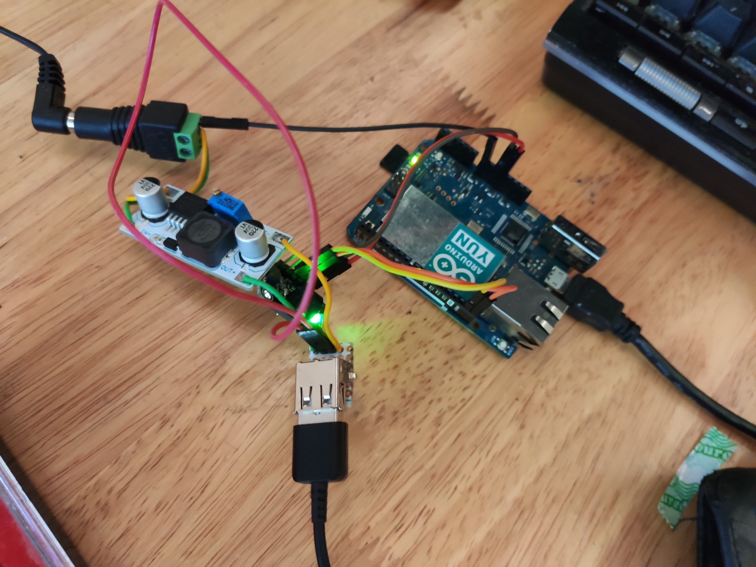
Many phones will draw high current if the USB data pins are shorted. Great news, I’ll do that 🙂 https://electronics.stackexchange.com/questions/123172/what-is-the-ideal-way-to-handle-data-pins-d-and-d-on-a-usb-power-adapter-to-be
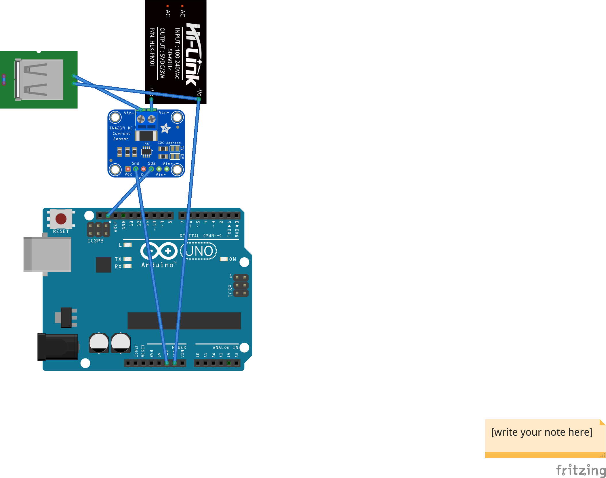
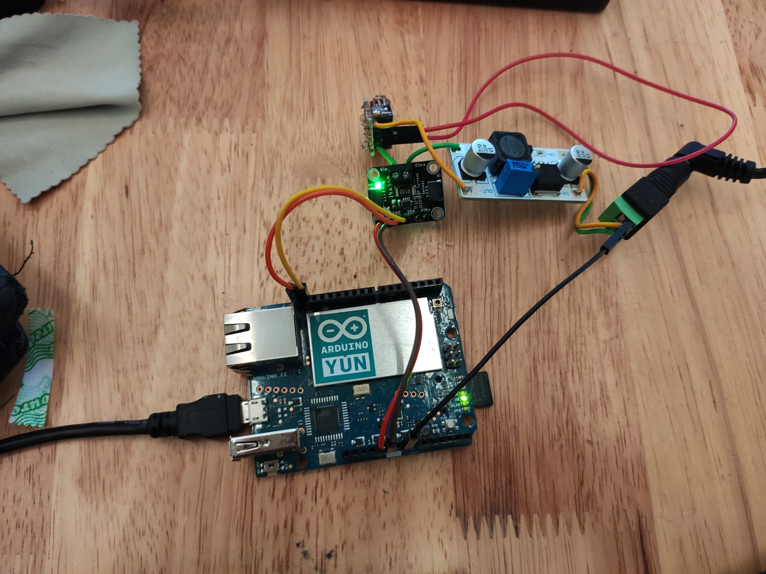
I used an INA219 breakout from Adafruit to measure the voltage and current, and logged the data using an Arduino (I used an old Yun — any one will do).
The power was first converted to 12 V by an ordinary AC-DC adapter. Then I used a Velleman variable voltage regulator to adjust the voltage around 5 V. It has a tiny screw that can be used to adjust the voltage.
Here’s a circuit diagram. The variable voltage regulator is represented here by the black box (Hi-Link). The INA219 is connected in series, after the positive output of the voltage regulator. The arduino is powered from the computer via USB, but the ground is connected to the ground of the system under test. Sorry for the crap quality:
I ran the program on the Arduino and opened the serial monitor. Then I slowly adjusted the voltage up and down. After having gone through the relevant voltages, I copied the output in the serial monitor into a text file, and then plotted it with a spreadsheet.
Results
- Redmi K20 phone – Battery state of charge 59 %

2. Samsung Tab 5 tablet – Battery state of charge 47 %C
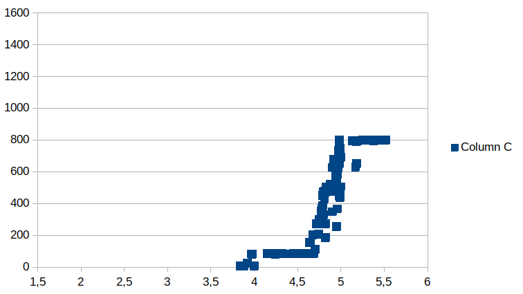
Some of the outliers are caused by a delayed response to changes in voltage.
The Redmi device pulled well over 1000 mA, and it seemed to continue to rise with input voltage. The Samsung device reaches a plateau at 5 V and stays there.
There is a point where the voltage is too low, and the current draw is limited to less than 100 mA. For the Redmi phone, it then won’t start drawing more current again until the voltage first goes very low (for example, by disconnecting it).
Conclusion
The current should ideally rise as the voltage approaches 5 V, and then remain at the safe charging current of the battery. Because the Li-ion charger inside the USB device steps down the voltage, the current drawn from the USB device should actually decrease, to maintain a constant current at the battery voltage. But staying constant would be quite okay, as getting 5.5 V or more is not something that should happen.
None of the two devices do this.
The Redmi device may have a charger that doesn’t properly deal with voltages > 5 V, because it keeps increasing the current. The USB supply voltage should be 5 V, so it would be a waste if it only does fast charging for wonky 5.5 V adapters. But on the plus side, it’s perfectly able to draw more than 1000 mA at 5 V, so it can charge pretty fast.
The Samsung device is clearly limited by software / firmware. It has a large battery that can definitely charge at a higher rate. Like many devices, it may require the data pins to be wired in a special way in order to allow the faster charging rate. Sure, it’s safe, but will be slow on most chargers.
The motivation was to see whether it’s possible to modulate the current draw by reducing the voltage. Indeed there’s a range between 4.5 and 5.0 V that can be used to almost linearly vary the current. Good news for the solar charger project (not introduced yet). Of course, I also can’t guarantee that the charging controller inside the phone can make sense of the varying voltage. Maybe something unsafe or damaging can happen when it comes back to 5 V after being lower.
Photos and code
Code is based on the example in the Adafruit INA219 library, just changed the output format.
#include <Wire.h>
#include <Adafruit_INA219.h>

Adafruit_INA219 ina219;
int i = 0;

void setup(void)
{
  Serial.begin(115200);
  while (!Serial) {
      // will pause Zero, Leonardo, etc until serial console opens
      delay(1);
  }

  uint32_t currentFrequency;

  Serial.println("Hello!");

  // Initialize the INA219.
  // By default the initialization will use the largest range (32V, 2A).  However
  // you can call a setCalibration function to change this range (see comments).
  if (! ina219.begin()) {
    Serial.println("Failed to find INA219 chip");
    while (1) { delay(10); }
  }
  // To use a slightly lower 32V, 1A range (higher precision on amps):
  //ina219.setCalibration_32V_1A();
  // Or to use a lower 16V, 400mA range (higher precision on volts and amps):
  //ina219.setCalibration_16V_400mA();

  Serial.println("Measuring volta     ge and current with INA219 ...");
}

void loop(void)
{
  float shuntvoltage = 0;
  float busvoltage = 0;
  float current_mA = 0;
  float loadvoltage = 0;
  float power_mW = 0;

  shuntvoltage = ina219.getShuntVoltage_mV();
  busvoltage = ina219.getBusVoltage_V();
  current_mA = ina219.getCurrent_mA();
  power_mW = ina219.getPower_mW();
  loadvoltage = busvoltage + (shuntvoltage / 1000);
  Serial.print(i);
  Serial.print('\t');
  Serial.print(busvoltage);
  Serial.print('\t');
  Serial.print(current_mA);
  Serial.println("");
 i++;
  delay(2000);
}